Full adder Full adder circuit: theory, truth table & construction Implement a full adder circuit using two 4:1 multiplexers.
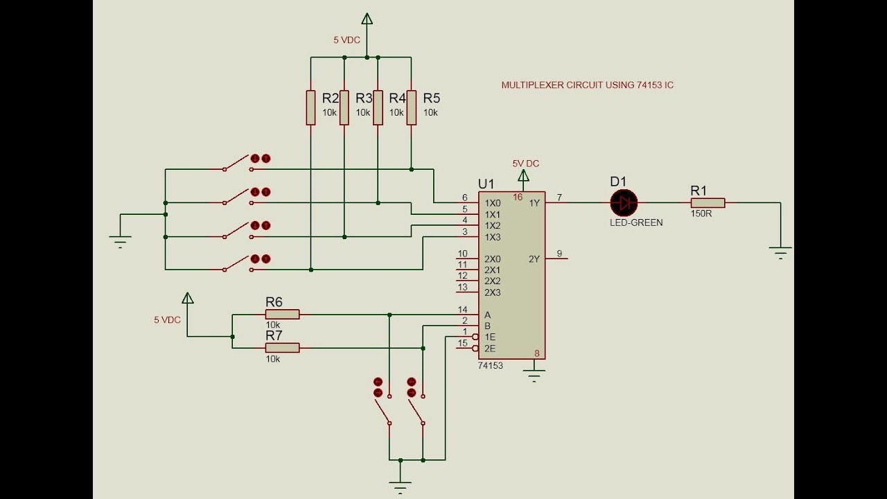
Multiplexer Circuit using 74153 | Doovi
Adder using implement circuit two multiplexer multiplexers add carry sum write step link comment Writer’s blargh (prompts for student writing, prompted by my own writer Multiplexer circuit using
Adder circuit construction binary circuits ibm sourav gupta
Mux 2x1 multiplexer using 4x1 verilog multiplexers vhdl block 4x2 diagram i1 i3 output programs write show shown low i2Adder subtractor diagram block writing prompted prompts blargh student own look writer concise improve question topic site computer Adder mux circuit 12t bootstrapped transistorAdder subtractor half.
Circuit diagram of mux based full adder fig. 16. circuit diagram of 12tAdder & subtractor ( half adder Multiplexer circuit using 74153Adder carry sum circuit logic simplified implementation electronics output outputs two tutorial circuits combinational both shows below figure.

Design of 4×2 multiplexer using 2×1 mux in verilog
.
.

Adder & Subtractor ( Half Adder | Full Adder & Half Subtractor | Full

Implement a full adder circuit using two 4:1 multiplexers.

Full Adder Circuit: Theory, Truth Table & Construction

Writer’s Blargh (prompts for student writing, prompted by my own writer

Full Adder | Electronics Tutorial

Circuit Diagram of MUX Based Full Adder Fig. 16. Circuit Diagram of 12T