Ece logic circuit A binary adder made using and-or array logic Adder circuit logic circuits figure x64 sonoma cs bob edu
logic gates - How to make 2 bit or more half adder circuit - Electrical
Adder logic sumador npn bjt aufbau transistoren construyendo transistores Adder adders libretexts circuits pageindex Circuits for binary arithmetic
Adder binary bit circuit rtl truth table example understand will need register use adders discuss details
Combinational circuitDigital logic: digital systems Adder additionneur binaire zpag electroniques gate sumLogic gates.
Adder bit circuit logic carry a1 stackexchange b1 xor a2Bit adder binary logic using array circuit input numbers carry adders two make add boolean finally put box Binary adder and binary addition using ex-or gatesAdder bit circuit half make logic diagram comparator gates first electronics questions cout second there only puzzle solved connecting which.

Full adder circuit diagram
Adder circuit combinational half logic wordAdder ripple xor adders rangkaian circuits transistor pengertian boolean kombinasi Binary adder circuit / circuit additionneur binaire5 logic circuits.
Circuit adder bit logic ece generate truth table now diagram numberA binary adder made using and-or array logic Adder (electronics)Adder logic binary circuit gates diagram using array make inputs twice labeled below also used.

Adder half binary addition logic bit diagram carry using vs adders truth table inputs gates python sum two program stackoverflow
Adder circuit logic using digital boolean function diagram implement implementationAdder binary combinatorial arithmetic resulting trivially strandh 4 bit binary adderDigital adder binary circuit bit systems building help circuits.
6.4: 2-bit adder circuit3 bit adder logic circuit design Digital logic design: full adder circuitWhat is parallel binary adder?.

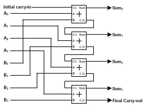
Adder binary parallel bit logic diagram circuit electronics between
.
.


Circuits for binary arithmetic

Combinational Circuit - Adder Circuits - NotesforMSc

Digital Logic Design: Full Adder Circuit

Full Adder Circuit Diagram

Binary adder circuit / Circuit additionneur binaire

What is Parallel Binary Adder? - 2-Bit and 5-Bit Parallel Binary Adder
A binary adder made using AND-OR array logic

Binary Adder and Binary Addition using Ex-OR Gates