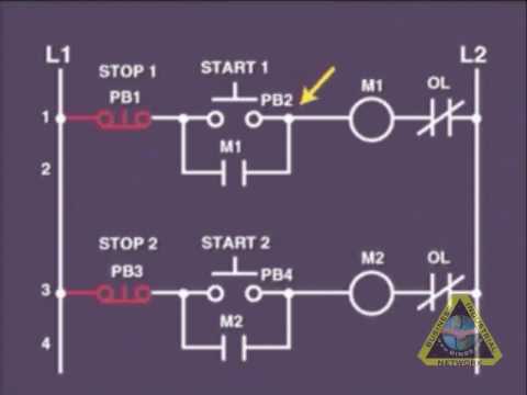
Wire circuit two control motor diagram three configuration gif electrical Ladder diagram basics #3 (2 wire & 3 wire motor control circuit) How a 3 phase motor control circuit works
6.7 2 and 3 Wire Control Circuits for Fluid Power Systems – Hydraulics
Wire motor control diagram circuit ladder basics Three-wire control circuit with indicator lamp Two wire & three wire motor control circuit
Circuits divided
Motor circuit diagram control wire phase three basicsCircuit control wire lamp three indicator wiring motor diagram ladder starter coil industrial when fig above energized added show [diagram] 2 wire control circuit diagram motor control basicsCircuit stop start diagram motor control wire two three multiple wiring jog starter switch electrical electricala2z stations configuration motors gif.
Circuit basics controlling reverse3 wire motor control 6.7 2 and 3 wire control circuits for fluid power systems – hydraulicsPhase motor circuit control works.
![[DIAGRAM] 2 Wire Control Circuit Diagram Motor Control Basics](https://i.ytimg.com/vi/wh9qSjhCVHE/maxresdefault.jpg)
Changeover wiring diagram
Wire ladder diagram control basicsMotor electrical stop start wire control wiring ac switch volt station schematic contractor simple forums discussion basic contactor overload thread Auxiliary contact wiring diagram rockwellTwo wire & three wire motor control circuit.
2 wire control circuit diagram. motor control basics. controlling threeMotor starter diagram phase wiring start stop control wire circuit three starting 480v electrical reversing voltage holding work electronic simple Motor starter diagram. start stop 3 wire control. starting a threeControl basic circuit dol starter direct line starting motor electrical circuits electric three hardwired system used contact main voltage.

3 wire motor control
Circuit control wire three start diagram motor button auxiliary ladder industrial push seal contacts coil connectedElectrical wiring diagram drawing changeover circuit control switch circuits phase tutorial motors generator automatic training limit electrician drawings Start/stop [3 wire] ac motor controlTroubleshooting three basic hardwired control circuits used in starting.
Starter auxiliary circuit reversing rockwell latching diagrams contactor eletrical dol ghisalba panel switches reverse6.7 2 and 3 wire control circuits for fluid power systems – hydraulics Three-wire control circuitControl wire circuit circuits hydraulic systems hydraulics electrical behavior describe.

Ladder diagram basics #3c 3 wire control
Wire control circuit systems hydraulics hydraulic electrical describe behaviorControl 220v contacts typical .
.


Troubleshooting three basic hardwired control circuits used in starting
![Start/Stop [3 wire] AC motor control - ECN Electrical Forums](https://i2.wp.com/www.electrical-contractor.net/theory/3wmc.gif)
Start/Stop [3 wire] AC motor control - ECN Electrical Forums
Changeover Wiring Diagram | Get Free Image About Wiring Diagram

How a 3 Phase Motor Control Circuit Works - YouTube

3 Wire Motor Control

3 Wire Motor Control

2 Wire Control Circuit Diagram. Motor Control Basics. Controlling three

Auxiliary Contact Wiring Diagram Rockwell