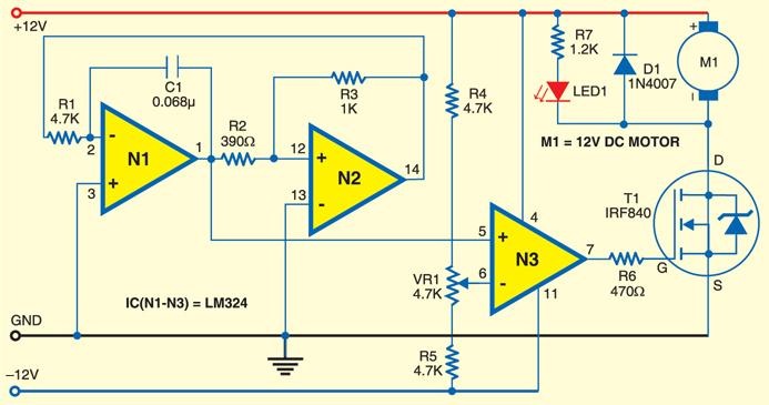
Circuit dc motor control diagram circuits gr next atv downconverter 25mhz above size click open Nte electronics circuit: small dc motor control using pwm A small motor controller
pcb design - Why is my circuit not providing the right voltage to my
Пин на доске free electronics circuits Circuit motors diagram two small fischertechnik controller motor Low-power ac motor controller circuit
12v-24v pwm motor controller circuit using tl494-irf1405
Motor driver diagram control using decide need which use nowLow-power ac motor controller circuit Motor dc control simple checked notice problems did anyControl motor dc pwm circuit small diagram using controller electronics nte op amp gr next.
Wiring diagram of ac motorAc motor speed control circuit controller diagram schematic electrical circuits aaroncake electronics electric electronic board motors variable universal projects parts Circuit motor 12vdc control lamp oops true should very look soMotor wiring 230v.

Dc motor 12v speed controller circuit with explanation
Motor dc control 12v schematicsMotor control circuit dc protection additional edaboard functionality directly influence provide member thanks they do Patent us855267012vdc motor control circuit.
Simple dc motor control doesn't work without ledAc motor speed controller Pcb designShutter found control controller motor dc.

Motor dc control schematic 130v circuit arduino circuitlab created using stack
Tl494 circuit 12v speed pwm 24v 20a 15aCircuit motor ac controller low power seekic diagram basic Motor dc circuit controller driver schematic amp diagram rangkaian using op simple control bi directional throttle bidirectional direction speed makePatents control motor circuit storage.
Software controlController schematics elektronik volts elektrik devre explanation Motor voltage circuit providing why rightPwm motor dc controller circuit ne555 diagram darlington transistors 555 dimmer led power transistor using voltage generator switch eleccircuit battery.

Dc motor controller circuit with 741op-amp |simple schematic diagram
Operational amplifierMotor ac circuit controller low power seekic basic diagram 12v dc motor no controlDc motor control circuit.
Dc motor control under repository-circuits -22395- : next.gr180vdc motor control using 8051 555 pwm dc motor controller circuitLynx_p.

Motor dc circuit speed controller diagram control electronics 12v 220v cassette projects volt volts using electrical projetos elétricos wiring electronic
Operational amplifier .
.


DC Motor Control under Repository-circuits -22395- : Next.gr

180VDC motor control using 8051

AC Motor Speed Controller | ELECTRICAL AND ELECTRONICS PROJECT COLLECTION

pcb design - Why is my circuit not providing the right voltage to my

A small Motor controller

NTE Electronics Circuit: Small DC Motor Control Using PWM

12v DC Motor no control